Blog
Fisher Space Systems LLC
Viper Rocket Trike
Updated Dec 2025
"Simplicity is the ultimate sophistication."
- Leonardo da Vinci
This work is licensed under the Creative Commons Attribution-ShareAlike 4.0 International License. To view a copy of this license,
visit
http://creativecommons.org/licenses/by-sa/4.0/
Copyright (c) 2021 Jerry F Fisher
http://creativecommons.org/licenses/by-sa/4.0/
Copyright (c) 2021 Jerry F Fisher

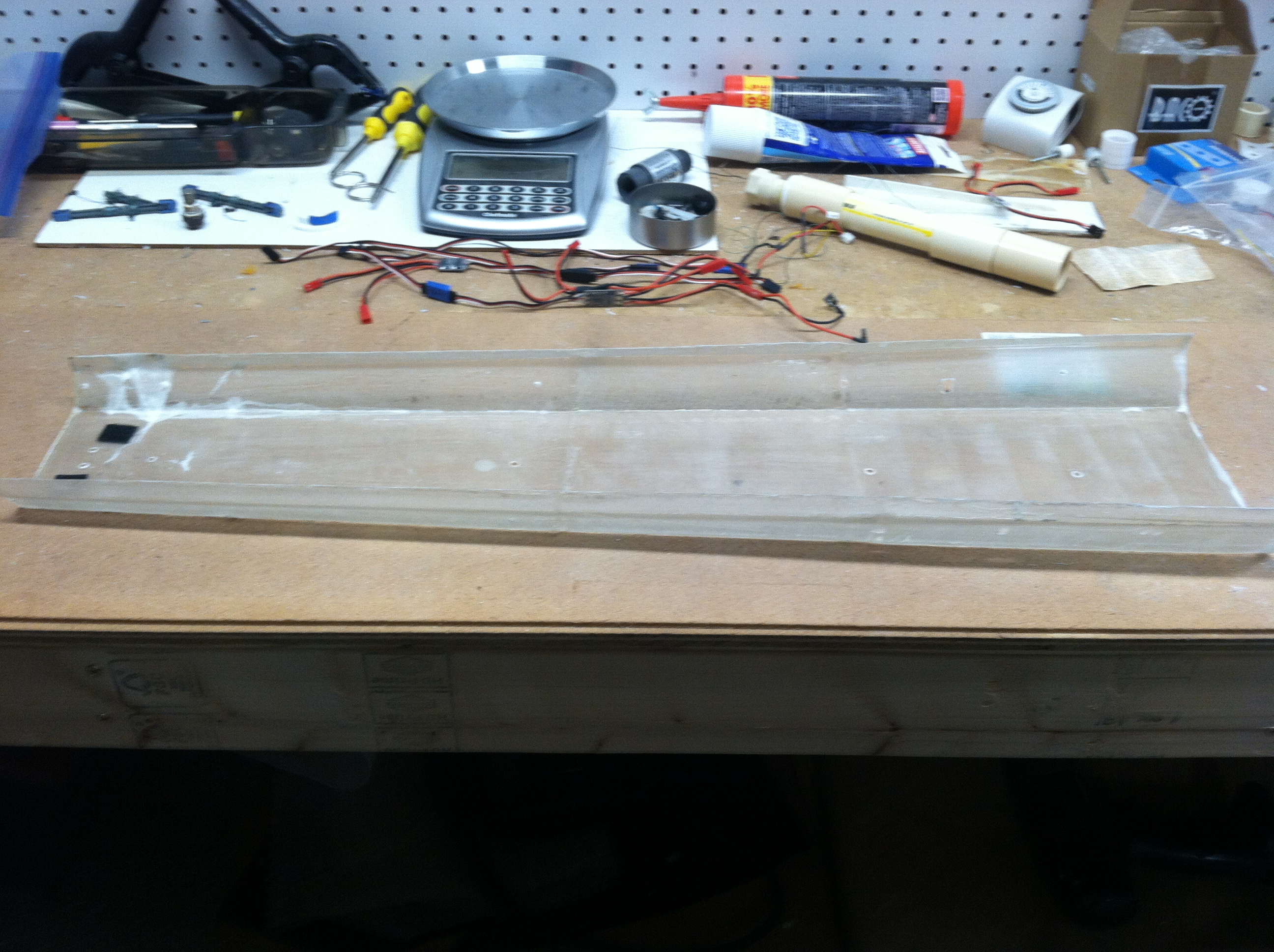
01-30-2025: No launch activity this month due to weather delays (to cold and snowy). Instead, I worked on cleaning and organizing my lab. I moved my workbench next to the wall so I could organize my tools. I plan to continue cleaning and organizing next month. I may get some static engine testing done if the weather cooperates. Read more in the Jan EOM Report.
03-31-2025: This month, I did a static test of the PLA fuel cores infused with a lower concentration of KMnO4. Ignition occurred in less than one second. Lower solubility means lower cost and lesser mess. Also, I did a MkI Viper launch using the larger styrofoam fins. The Viper still pitched up but not as much. The addition of ventral nacelles will introduce drag at the port and starboard fins counteracting the pitch up. Read more in the Mar EOM Report.
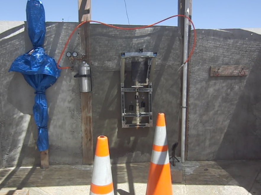
04-30-2025: This month, I did two static tests of the PLA fuel cores infused with a lower concentration of KMnO4. This was the 4th infusion of KMnO4 using the original solubility of 50 gm/L. In the first test, ignition occurred in less than one second due primarily to a small leak in the solenoid valve. In the second test, a larger leak in the solenoid resulted in an explosion.
The ignition test of the 4th infusion was inconclusive. However, I surmised that by using a motorized ball valve on the class II engine, I can scale the engine to higher thrust by leaking HTP into the fuel core thus preheating the fuel core prior to ignition.
05-31-2025: This month, I had two launch attempts of the MkI Viper rocket glider. On the first launch attempt, the Viper just barely cleared the rail guide and fell to the concrete floor. I had a massive leak at the propellant tank connection. In the second launch attempt, the Viper cleared the rail guide and made it to ~ 30 feet while yawing to port, a new record for Fisher Space Systems, LLC.
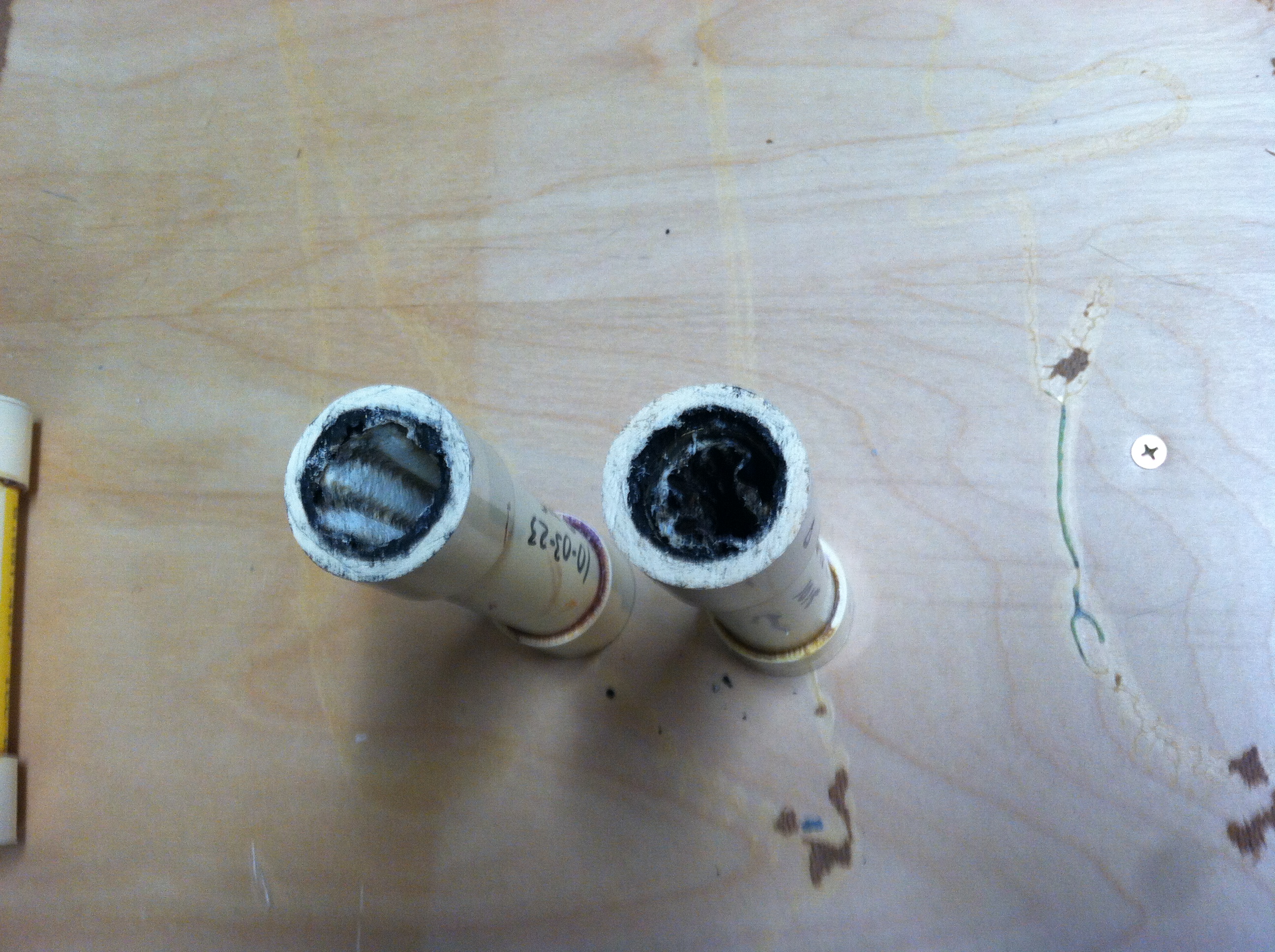
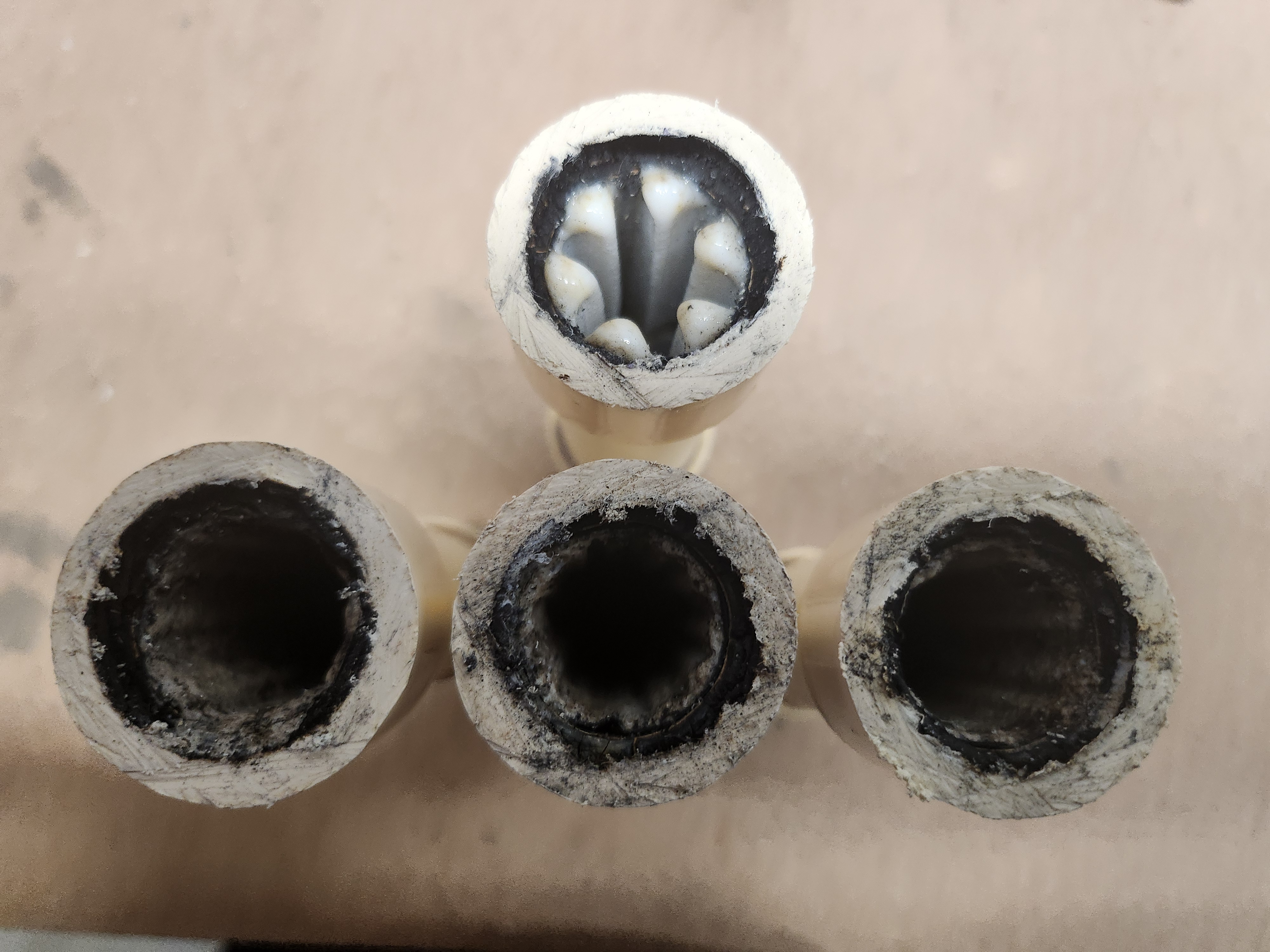
06-30-2025: This month, I had one launch of the MkI Viper rocket glider. The Viper cleared the rail guide at ~ 3.6 m/sec and reached an altitude of ~ 100 feet while arcing over and heading east. The Viper exhausted all of the unstabilized HTP oxidizer in this launch before crashing into the ground, a first for Fisher Space Systems, LLC. Analysis of the spent fuel core showed an almost complete burn of available PLA/KMnO4. I plan a series of test to determine what effect HTP stabilizers play in the combustion efficiency of PLA.
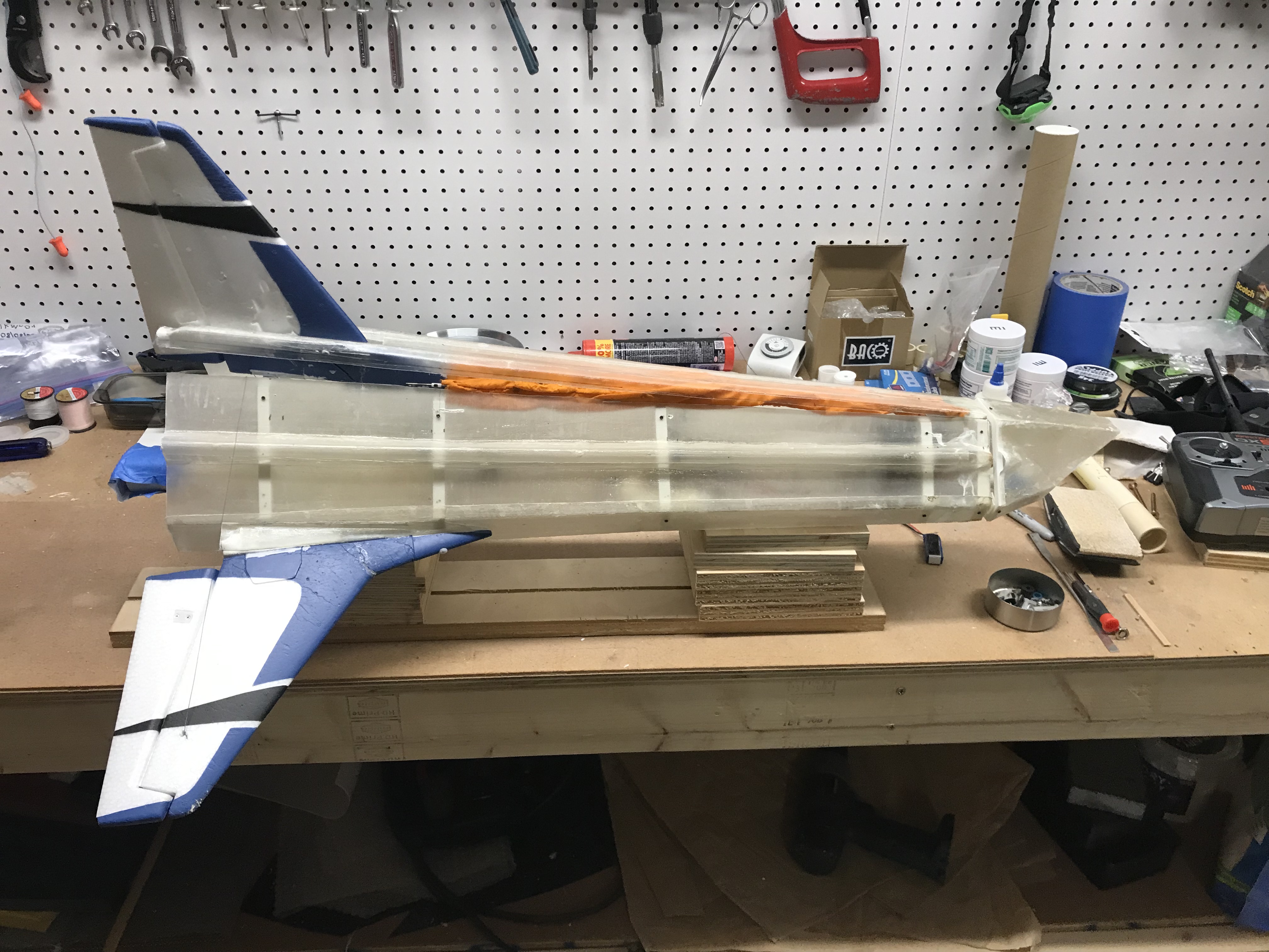
07-31-2025: This month, I had two launches of the MkI Viper rocket glider. In the first launch, the Viper cleared the rail guide at ~ 3.0 m/sec. The Viper pitched down and crashed into the ground. I rebuilt the frame and fuselage. The fuselage was further streamlined. The next launch of the Viper cleared the rail guide at greater than 4.0 m/sec. I had aerodynamic control, no pitch and no roll until ~ 30 ft. The propellants expended before landing and I was able to actuate the canopy release.
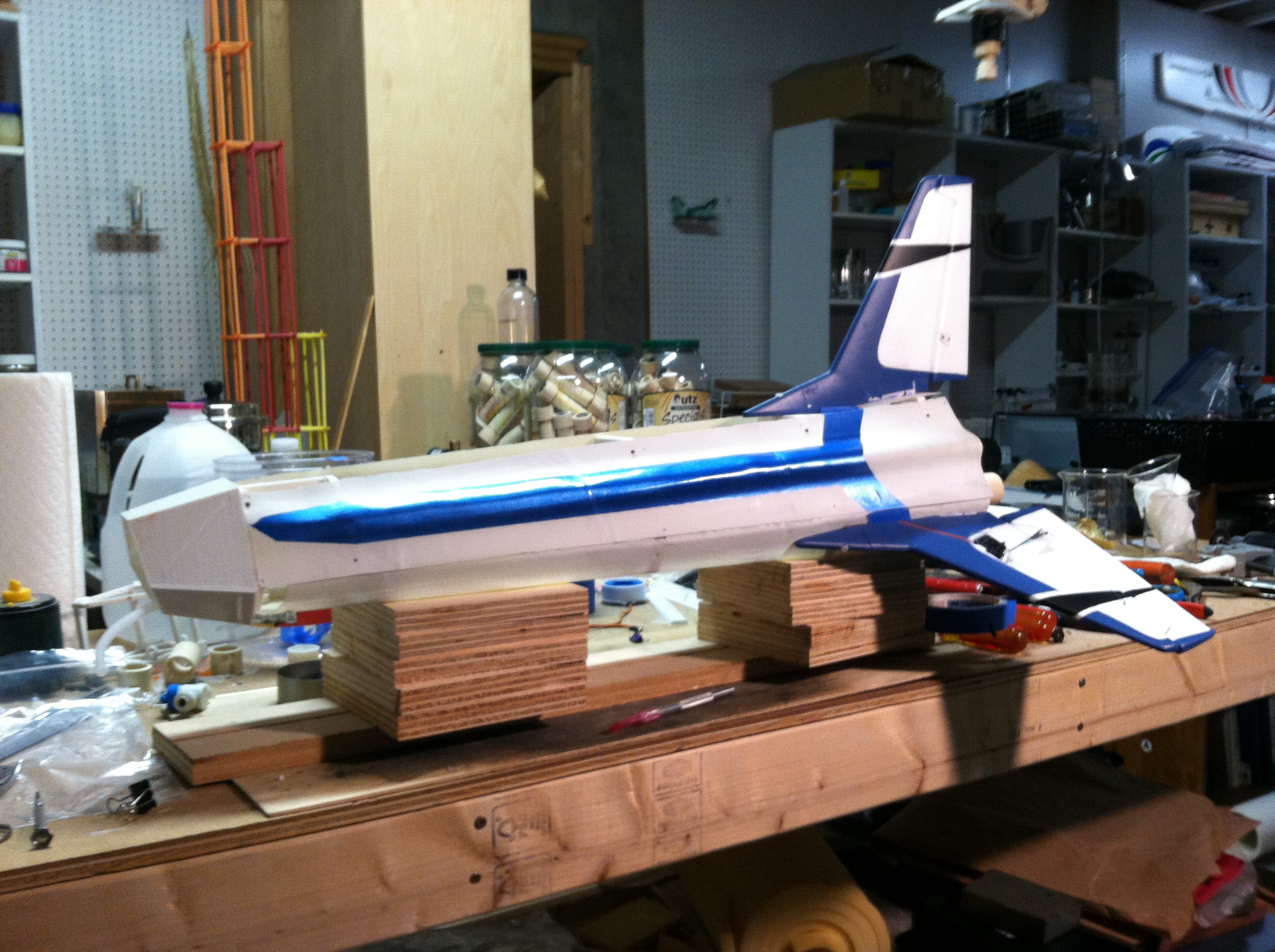
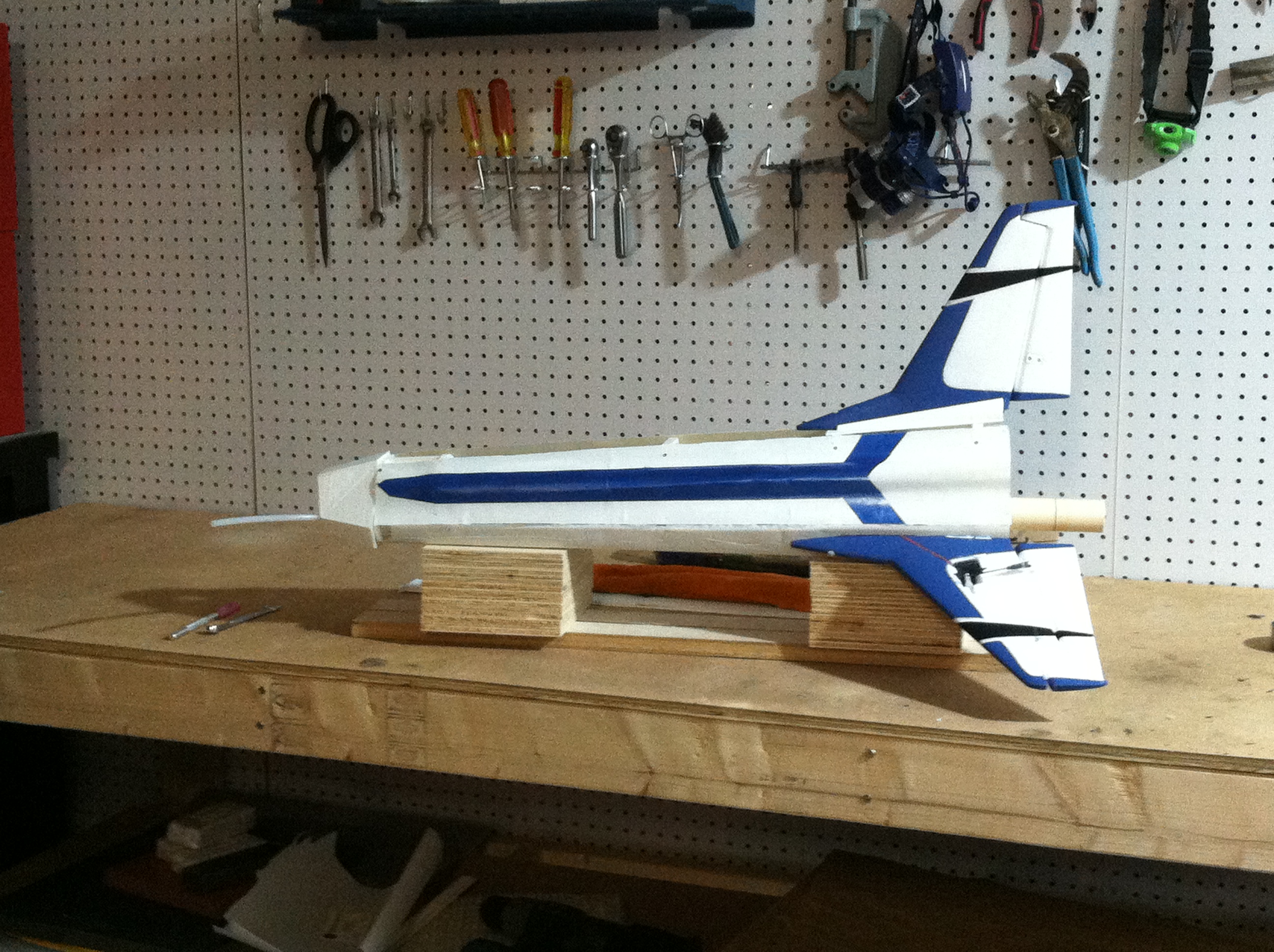
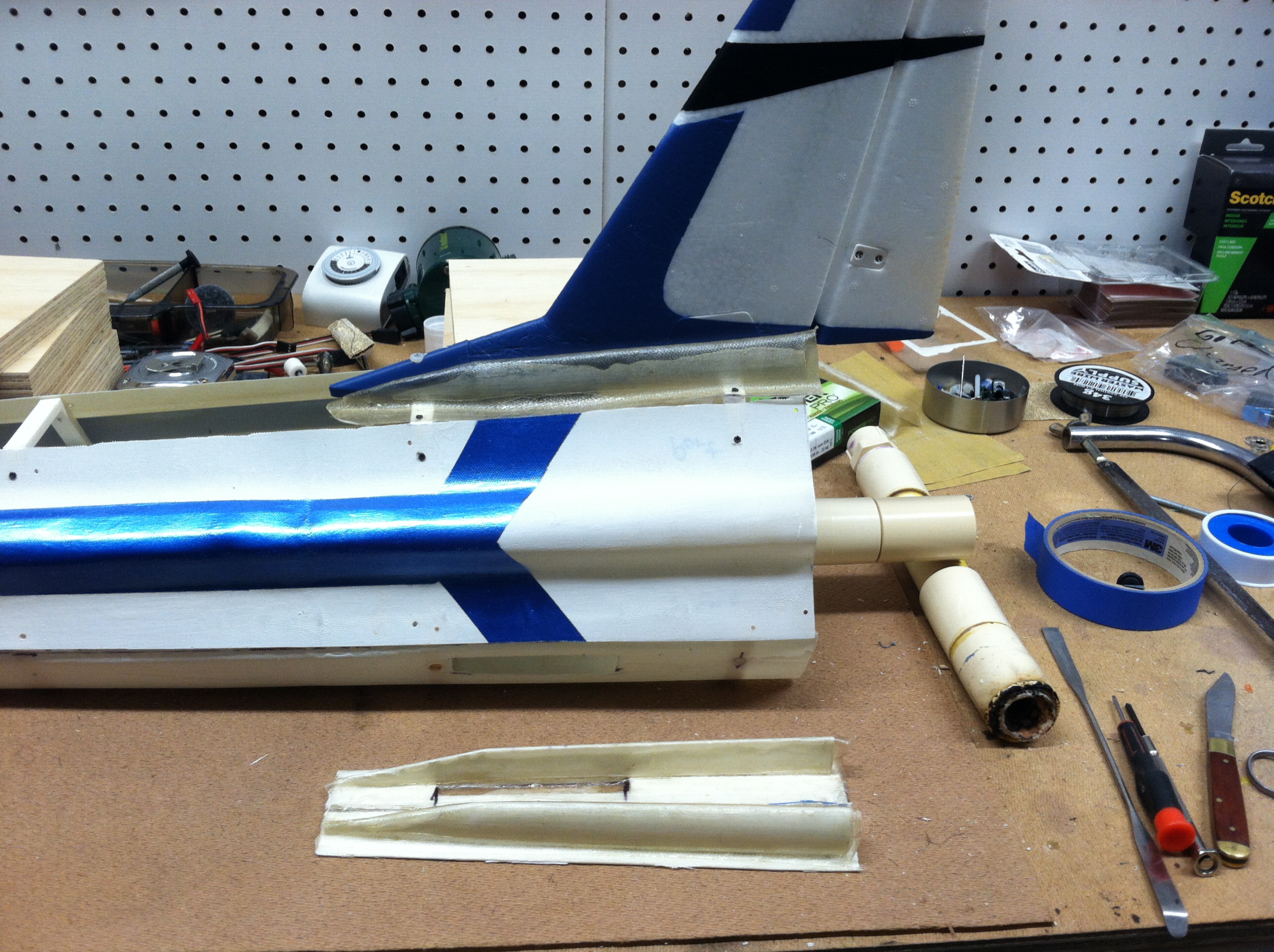
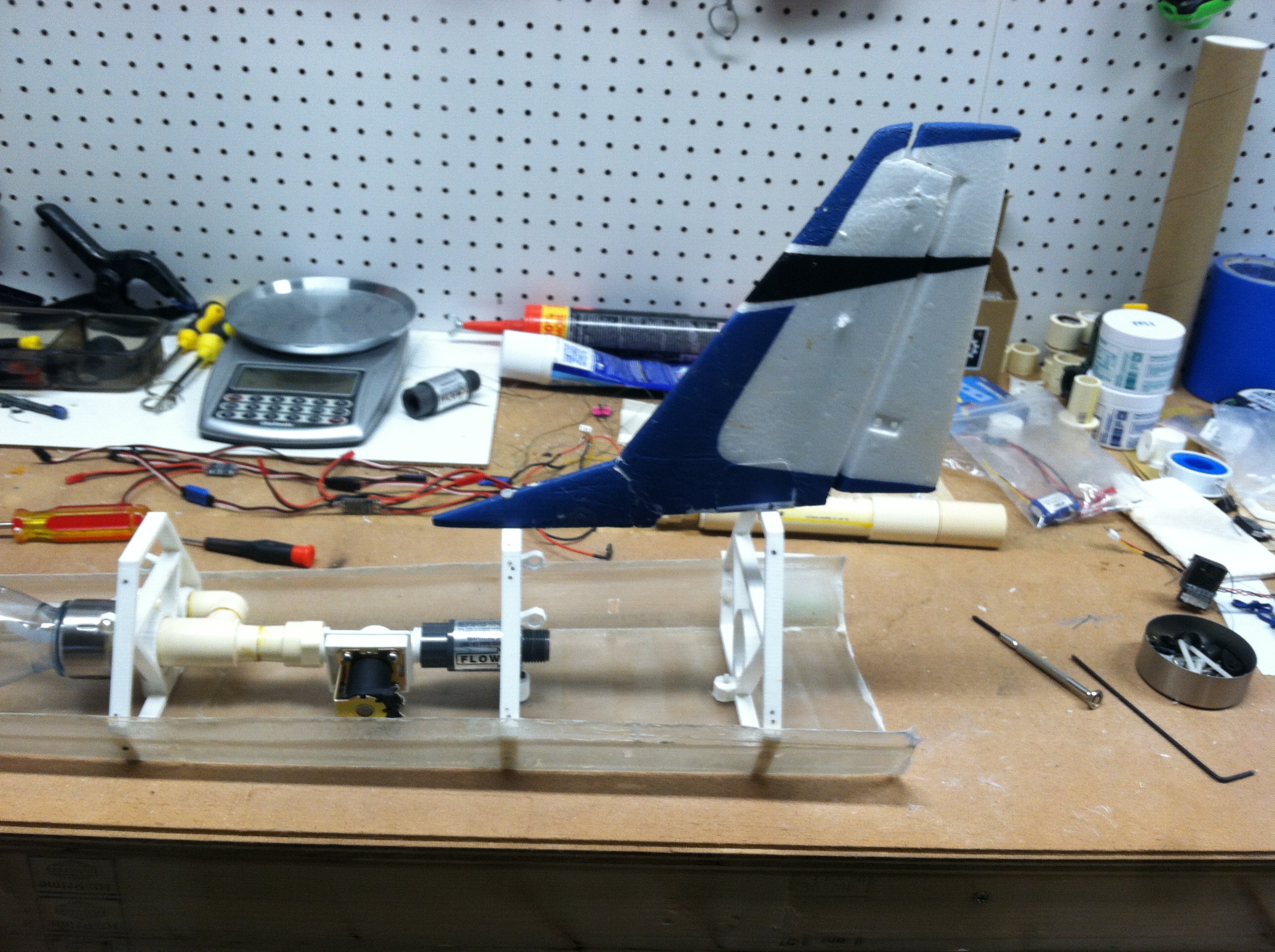
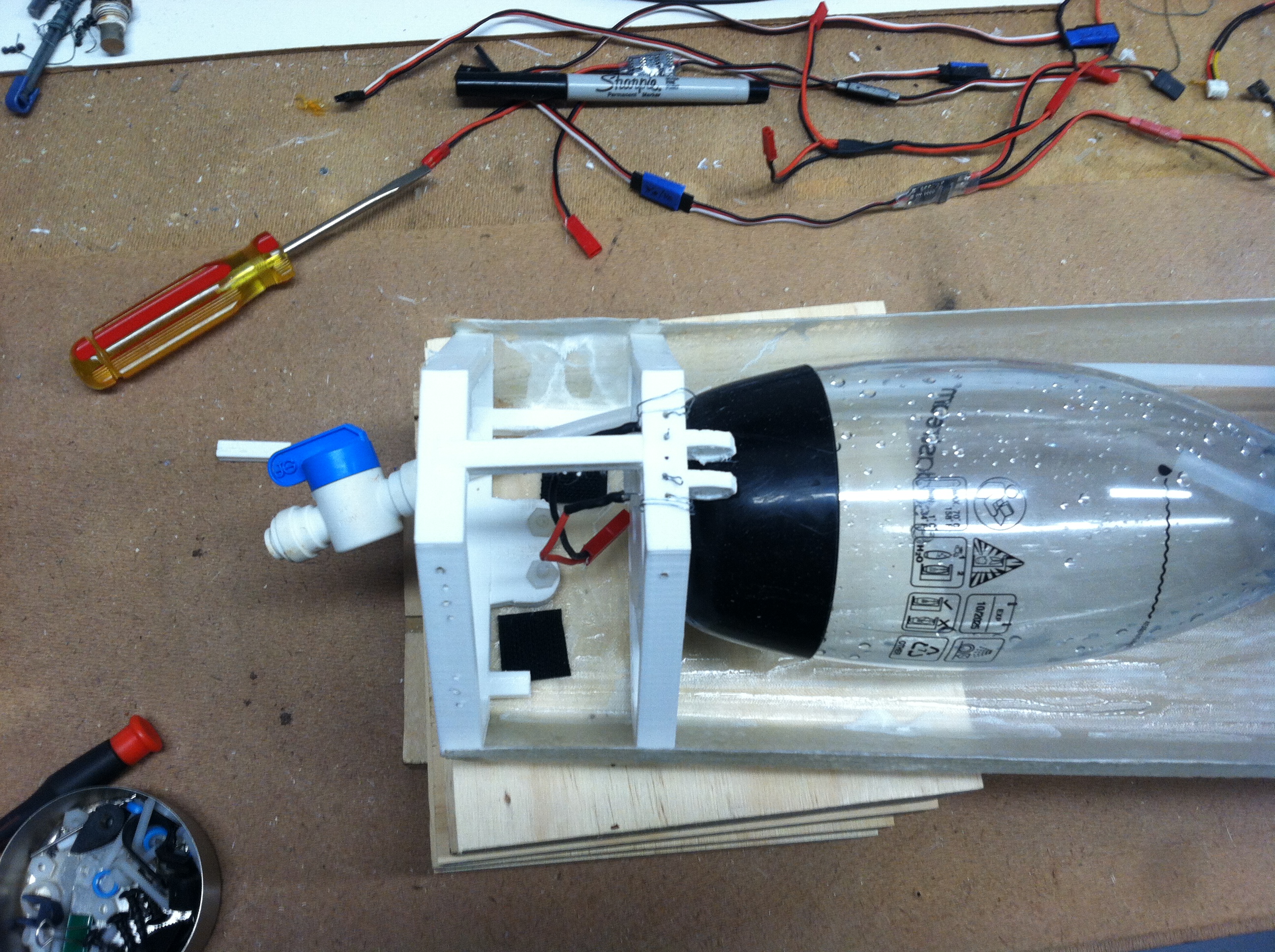
08-31-2025: This month, I had one launch attempt of the MkI Viper rocket glider. I flipped the switch on the transmitter and no ignition. There was a short in one of the switches. This destroyed the receiver, two servos, and one switch. I had to order new parts. In the mean time, I continued with streamlining the MkI Viper and took some pictures of the assembly process.
09-30-2025: This month, I had three launch attempts of the MkI Viper rocket glider with no ignition. I surmise that I have reached the lower concentration limit for infusion of KMnO4 into PLA. As such, I'm returning to a concentration of 50 gm/L.
10-31-2025: This month, I had three launch attempts of the MkI Viper rocket glider. The first launch attempt, I used the fuel cores from the second infusion at 40 gm/L, I did not have ignition. I had two successful launches using the fuel cores from the first infusion at 50 gm/L. This further suggest that the concentration level is to low. Also this month, I've noticed a greater PLA mass flow rate using the lower concentration. The O/F ratio dropped from 3.0 to 2.3. Finally, I started working on scaling factors for a class II rocket engine.
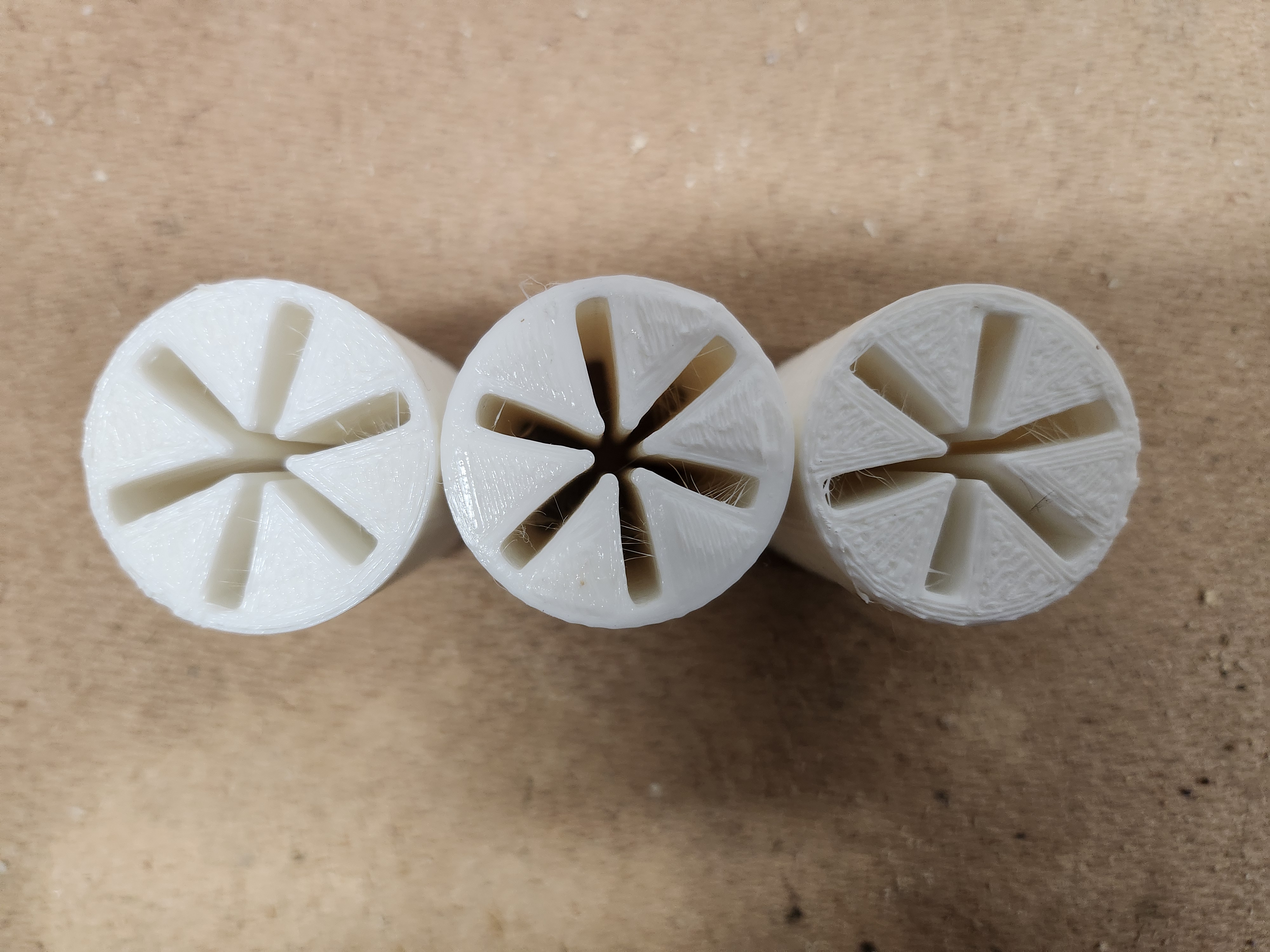
11-30-2025: The enhanced burn is not due to the lower concentration of KMnO4 infused into the PLA. It is due to a 20% infill in the PLA fuel core (a mistake in the printing). In the most recent test, the O/F ratio was ~ 1.3. This is about half of theoretical. Is there an optimum infill? The capability to vary the infill for a hybrid fuel core is unique to 3D printing.
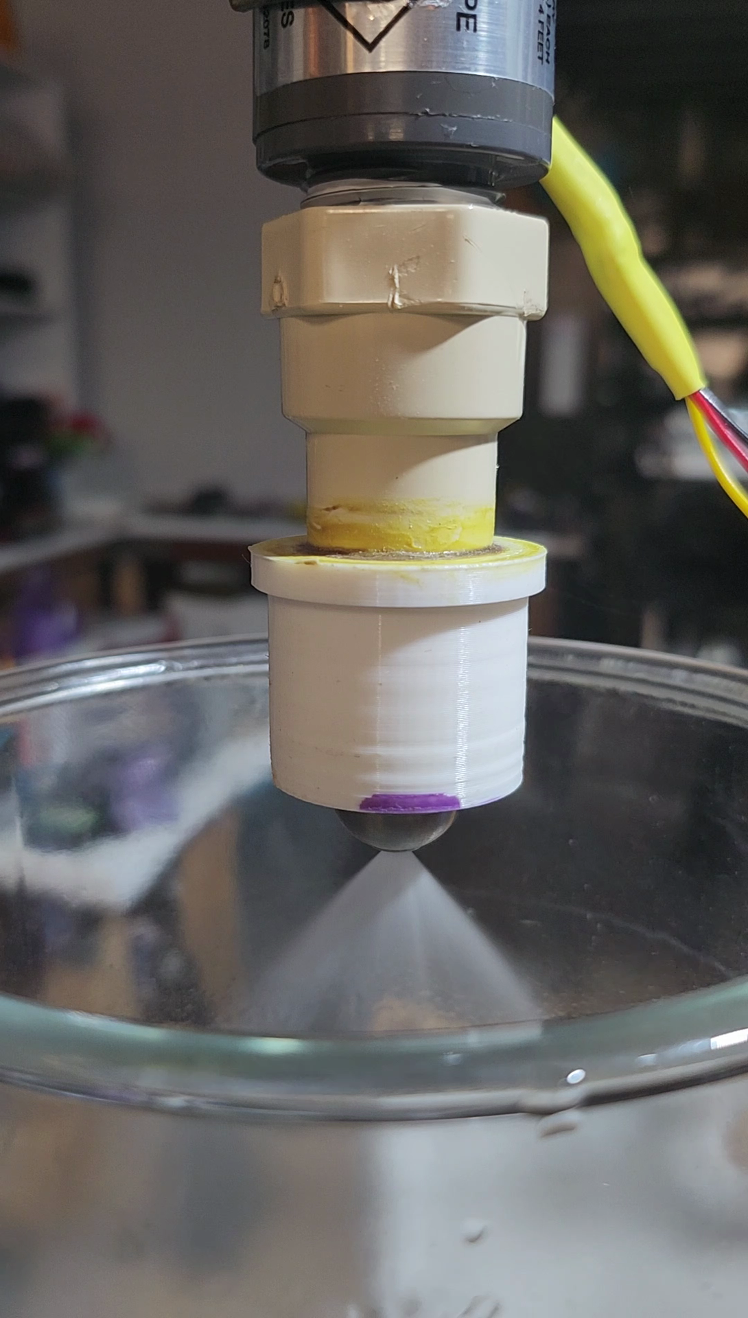
12-31-2025: This month, I worked on upgrading from my plastic solenoid valve with a mass of ~ 94 gm with a stainless steel motorized ball valve with a mass of ~ 330 gm. As soon as I add a motorized ball valve, I have transition to a Class II rocket motor.
03-31-2025: This month, I did a static test of the PLA fuel cores infused with a lower concentration of KMnO4. Ignition occurred in less than one second. Lower solubility means lower cost and lesser mess. Also, I did a MkI Viper launch using the larger styrofoam fins. The Viper still pitched up but not as much. The addition of ventral nacelles will introduce drag at the port and starboard fins counteracting the pitch up. Read more in the Mar EOM Report.
04-30-2025: This month, I did two static tests of the PLA fuel cores infused with a lower concentration of KMnO4. This was the 4th infusion of KMnO4 using the original solubility of 50 gm/L. In the first test, ignition occurred in less than one second due primarily to a small leak in the solenoid valve. In the second test, a larger leak in the solenoid resulted in an explosion.
The ignition test of the 4th infusion was inconclusive. However, I surmised that by using a motorized ball valve on the class II engine, I can scale the engine to higher thrust by leaking HTP into the fuel core thus preheating the fuel core prior to ignition.
05-31-2025: This month, I had two launch attempts of the MkI Viper rocket glider. On the first launch attempt, the Viper just barely cleared the rail guide and fell to the concrete floor. I had a massive leak at the propellant tank connection. In the second launch attempt, the Viper cleared the rail guide and made it to ~ 30 feet while yawing to port, a new record for Fisher Space Systems, LLC.
06-30-2025: This month, I had one launch of the MkI Viper rocket glider. The Viper cleared the rail guide at ~ 3.6 m/sec and reached an altitude of ~ 100 feet while arcing over and heading east. The Viper exhausted all of the unstabilized HTP oxidizer in this launch before crashing into the ground, a first for Fisher Space Systems, LLC. Analysis of the spent fuel core showed an almost complete burn of available PLA/KMnO4. I plan a series of test to determine what effect HTP stabilizers play in the combustion efficiency of PLA.
07-31-2025: This month, I had two launches of the MkI Viper rocket glider. In the first launch, the Viper cleared the rail guide at ~ 3.0 m/sec. The Viper pitched down and crashed into the ground. I rebuilt the frame and fuselage. The fuselage was further streamlined. The next launch of the Viper cleared the rail guide at greater than 4.0 m/sec. I had aerodynamic control, no pitch and no roll until ~ 30 ft. The propellants expended before landing and I was able to actuate the canopy release.
08-31-2025: This month, I had one launch attempt of the MkI Viper rocket glider. I flipped the switch on the transmitter and no ignition. There was a short in one of the switches. This destroyed the receiver, two servos, and one switch. I had to order new parts. In the mean time, I continued with streamlining the MkI Viper and took some pictures of the assembly process.
09-30-2025: This month, I had three launch attempts of the MkI Viper rocket glider with no ignition. I surmise that I have reached the lower concentration limit for infusion of KMnO4 into PLA. As such, I'm returning to a concentration of 50 gm/L.
10-31-2025: This month, I had three launch attempts of the MkI Viper rocket glider. The first launch attempt, I used the fuel cores from the second infusion at 40 gm/L, I did not have ignition. I had two successful launches using the fuel cores from the first infusion at 50 gm/L. This further suggest that the concentration level is to low. Also this month, I've noticed a greater PLA mass flow rate using the lower concentration. The O/F ratio dropped from 3.0 to 2.3. Finally, I started working on scaling factors for a class II rocket engine.
11-30-2025: The enhanced burn is not due to the lower concentration of KMnO4 infused into the PLA. It is due to a 20% infill in the PLA fuel core (a mistake in the printing). In the most recent test, the O/F ratio was ~ 1.3. This is about half of theoretical. Is there an optimum infill? The capability to vary the infill for a hybrid fuel core is unique to 3D printing.
12-31-2025: This month, I worked on upgrading from my plastic solenoid valve with a mass of ~ 94 gm with a stainless steel motorized ball valve with a mass of ~ 330 gm. As soon as I add a motorized ball valve, I have transition to a Class II rocket motor.